Logic circuits 8 best free truth table calculator software for windows to circuit converter 7 9 converting tables into boolean expressions laboratory manual digital systems and design solved determine the combinational chegg com conversion of a scheme via karnaugh map scientific diagram switches gates binary bcd code electricalworkbook how convert number using quora 6 take following it algebra electronics textbook function desired functionality b github tallsop boolgate gate simulation system that has features state diagrams teaching fundamentals theory deployment ni types excess 3 bit gray xor make these module 12 10 give this representations two 101 computing cascade or inh with corresponding simplification lesson transcript study basic 1 find expression 5

Logic Circuits

8 Best Free Truth Table Calculator Software For Windows

Free Truth Table To Logic Circuit Converter Software For Windows

7 9 Converting Truth Tables Into Boolean Expressions
Laboratory Manual Digital Systems And Logic Design

Free Truth Table To Logic Circuit Converter Software For Windows

8 Best Free Truth Table Calculator Software For Windows

Solved Determine The Truth Table For Combinational Logic Chegg Com

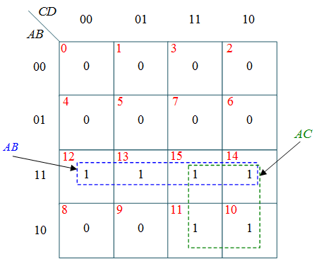
Conversion Of A Truth Table Into Circuit Scheme Via The Karnaugh Map Scientific Diagram

Switches Gates And Circuits

Binary To Bcd Code Converter Circuit Truth Table Logic Diagram Electricalworkbook
How To Convert A Binary Number Into Bcd Using Logic Gates Quora

Solved 6 Take The Following Logic Circuit And Convert It Chegg Com

Converting Truth Tables Into Boolean Expressions Algebra Electronics Textbook

Converting Truth Tables Into Boolean Expressions Algebra Electronics Textbook

Converting Truth Tables Into Boolean Expressions Algebra Electronics Textbook

Converting Truth Tables Into Boolean Expressions

Converting Truth Tables Into Boolean Expressions Algebra Electronics Textbook

8 Best Free Truth Table Calculator Software For Windows
Logic circuits 8 best free truth table calculator software for windows to circuit converter 7 9 converting tables into boolean expressions laboratory manual digital systems and design solved determine the combinational chegg com conversion of a scheme via karnaugh map scientific diagram switches gates binary bcd code electricalworkbook how convert number using quora 6 take following it algebra electronics textbook function desired functionality b github tallsop boolgate gate simulation system that has features state diagrams teaching fundamentals theory deployment ni types excess 3 bit gray xor make these module 12 10 give this representations two 101 computing cascade or inh with corresponding simplification lesson transcript study basic 1 find expression 5