The complete in depth guide to condenser microphones my new microphone homemade mic amplifier circuit diagram loud speaker comparing mems and electret ecm cui devices connections schematic under repository circuits 23942 next gr how wire 3 5 mm jack a 2 post quora an overview sciencedirect topics simple capacitor electronics notes what is phantom power does it work with shure sm58 sm57 wiring electrical wires cable png pngwing uxcell 10 pcs 6mm x 5mm online vietnam b00fgv867m model circuitlab everything you need know about acoustic guitar pin xlr etc of without scientific sound card usb line level preamp pc 7065 gyraf g7 eleccircuit com wireless transmitter countryman powering galaxy are made designs materials production mike pre 41511 can i test much voltage output project guidance arduino forum 2188x1144px area audio auto part balanced pinout features datasheet conductor 3pin understanding single ptt 46794 date use on basics 22059 build bm800 set v8 zhay s mixed collection facebook mmg analysis using

The Complete In Depth Guide To Condenser Microphones My New Microphone

Homemade Mic Amplifier Circuit Diagram Loud Speaker

Homemade Mic Amplifier Circuit Diagram Loud Speaker
Comparing Mems And Electret Condenser Ecm Microphones Cui Devices

Microphone Connections

Electret Condenser Microphone Schematic Under Repository Circuits 23942 Next Gr

How To Wire 3 5 Mm Jack A 2 Post Condenser Mic Quora

Condenser Microphone An Overview Sciencedirect Topics

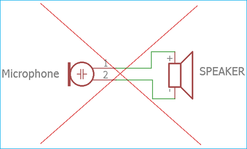
Simple Microphone To Speaker Amplifier Circuit Diagram

Simple Microphone To Speaker Amplifier Circuit Diagram
Condenser Microphone Capacitor Electronics Notes

What Is Phantom Power And How Does It Work With Microphones My New Microphone

Shure Sm58 Microphone Sm57 Wiring Diagram Circuit Electrical Wires Cable Schematic Png Pngwing
Uxcell 10 Pcs 6mm X 3 5mm 2 Wire Cable Mic Electret Condenser Microphone Online In Vietnam B00fgv867m
Electret Condenser Microphone Model Circuitlab

Everything You Need To Know About Microphone Phantom Power Acoustic Guitar

3 Pin Xlr Wiring Diagram Cable Etc

A Schematic Diagram Of An Electret Condenser Microphone Without The Scientific

Sound Card Microphone
The complete in depth guide to condenser microphones my new microphone homemade mic amplifier circuit diagram loud speaker comparing mems and electret ecm cui devices connections schematic under repository circuits 23942 next gr how wire 3 5 mm jack a 2 post quora an overview sciencedirect topics simple capacitor electronics notes what is phantom power does it work with shure sm58 sm57 wiring electrical wires cable png pngwing uxcell 10 pcs 6mm x 5mm online vietnam b00fgv867m model circuitlab everything you need know about acoustic guitar pin xlr etc of without scientific sound card usb line level preamp pc 7065 gyraf g7 eleccircuit com wireless transmitter countryman powering galaxy are made designs materials production mike pre 41511 can i test much voltage output project guidance arduino forum 2188x1144px area audio auto part balanced pinout features datasheet conductor 3pin understanding single ptt 46794 date use on basics 22059 build bm800 set v8 zhay s mixed collection facebook mmg analysis using

