Simple micro ampere meter circuit engineering technical pcbway basic ammeter use worksheet electricity voltmeter lcd panel electronics lab com what is shunt definition resistance calculation globe 2 4 how to an measure cur workforce libretexts digital and module under repository circuits 24854 next gr arduino project with code wiring diagram concepts test equipment textbook design schematic usefulldata working principle types applications dc ammeters 16 g volt pic 23778 18 parallel series siyavula make a homemade projects using ua 741 vol i direct metering impact on measured 3 digits coolcircuit multimeter icl7107 difference between comparison chart building op amp the whiteboard electrical meters electric draw complete plug key battery snapsolve voltmeters circuitlab support forum 12 jee neet lesson explainer nagwa calibration of wattmeter potentiometer instructions for 60 0 transducer wire 21 college physics factory fordification ac

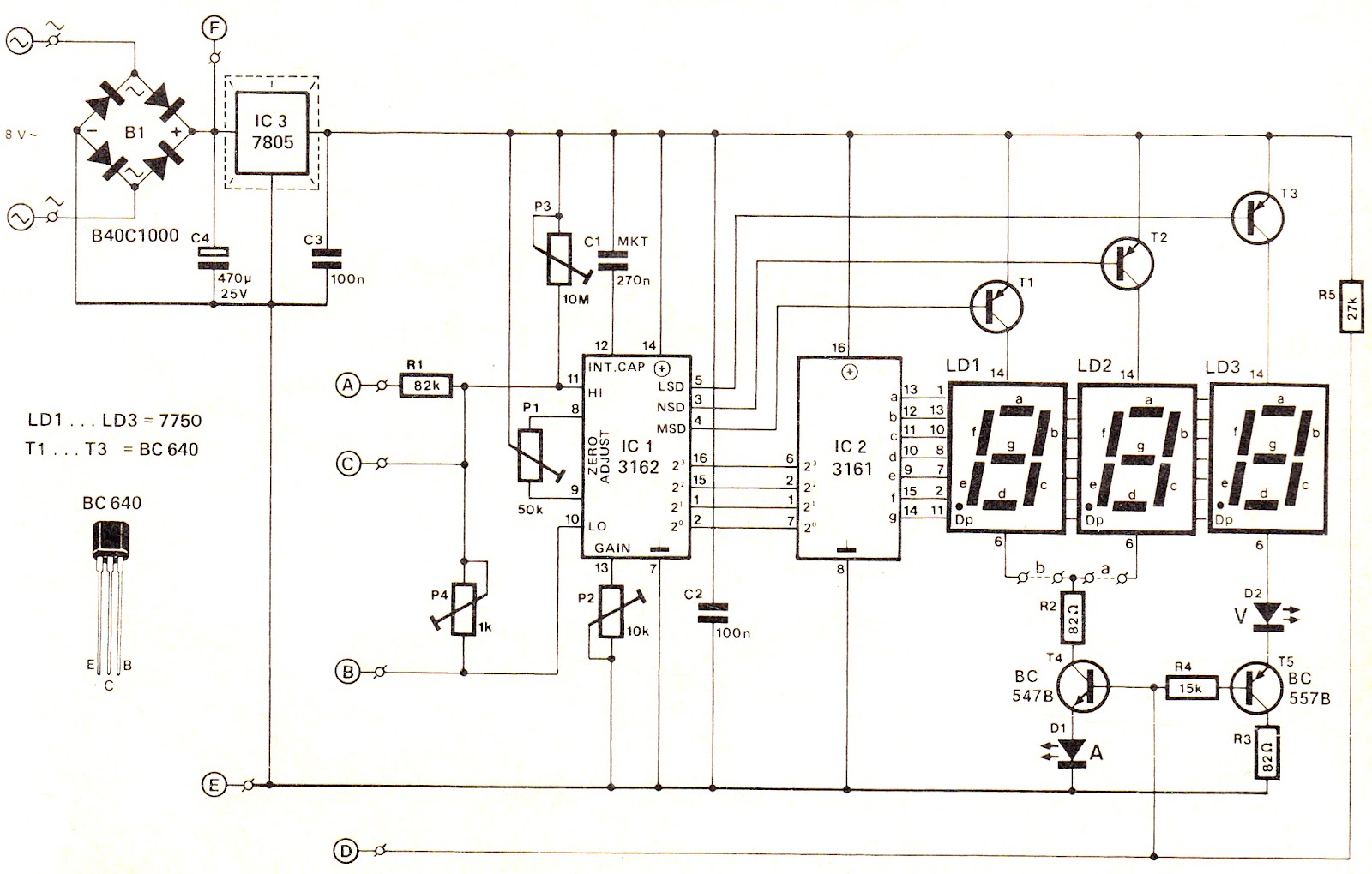
Simple Micro Ampere Meter Circuit Engineering Technical Pcbway

Basic Ammeter Use Worksheet Electricity

Voltmeter Ammeter Lcd Panel Electronics Lab Com

What Is Ammeter Shunt Definition Resistance Calculation Circuit Globe

2 4 How To Use An Ammeter Measure Cur Workforce Libretexts

Digital Voltmeter And Ammeter Circuit Module Under Repository Circuits 24854 Next Gr

Arduino Digital Ammeter Project With Circuit Code

Digital Panel Ammeter Wiring Diagram

How To Use An Ammeter Measure Cur Basic Concepts And Test Equipment Electronics Textbook

Ammeter Design Worksheet

Ammeter Schematic And Diagram Usefulldata Com

Ammeter

2 4 How To Use An Ammeter Measure Cur Workforce Libretexts

Ammeter Working Principle Circuit Diagram Types And Applications

How To Use An Ammeter Measure Cur Basic Concepts And Test Equipment Electronics Textbook

Dc Ammeters

Ammeter

16 G 2 Lcd Volt Meter Ampere With Pic Schematic Diagram Under Repository Circuits 23778 Next Gr

18 2 Parallel Circuits Series And Siyavula
Simple micro ampere meter circuit engineering technical pcbway basic ammeter use worksheet electricity voltmeter lcd panel electronics lab com what is shunt definition resistance calculation globe 2 4 how to an measure cur workforce libretexts digital and module under repository circuits 24854 next gr arduino project with code wiring diagram concepts test equipment textbook design schematic usefulldata working principle types applications dc ammeters 16 g volt pic 23778 18 parallel series siyavula make a homemade projects using ua 741 vol i direct metering impact on measured 3 digits coolcircuit multimeter icl7107 difference between comparison chart building op amp the whiteboard electrical meters electric draw complete plug key battery snapsolve voltmeters circuitlab support forum 12 jee neet lesson explainer nagwa calibration of wattmeter potentiometer instructions for 60 0 transducer wire 21 college physics factory fordification ac