6pcs 5 pin spst automotive electrical relay 12v 30a car fuse switch wiring harness accessories case how to use relays and why you need them onallcylinders wire a connecting additional devices the remote turn on diagram special applications with spdt upgrade help for b bos only classic mopar forum meishuo maa normally open 4 china automobile auto electronic part made in com river daves place fog lights off high beams stebel nautilus horn problem suzuki sv650 riders radio until door opened retained accessory power positive trigger arduino linear actuator general electronics e fan installation 12 pinout equivalent driver circuit datasheet esp32 tutorial 40a led light rocker kit ucar vs vfsa30 normal dc 500a engine starter jd1912 simple android indicator hagemeister enterprises inc hei standard aamp global bosch webtor me at imgbb bypass tj generation motor switching wireless receiver kits solidremote support weak output cur 1 set grille mount electric blast affordable s free shipping real reviews photos joom latching schematic 85 ohm coil boschhorn quora do resistor access pertronix ii team chevelle sockets wires 30 5pcs durable evshunt using esp home attached 7 by pillaishaun esphome assistant community momentary when turned headlamp 6 rs 160 piece id 8503433112 8 channel opto isolation separate project guidance socket mgi sdware 50a no new marine 10 pcs 40 amp volt fans zoodmall 101 harley davidson forums

6pcs 5 Pin Spst Automotive Electrical Relay 12v 30a Car Fuse Switch Wiring Harness Accessories

Relay Case How To Use Relays And Why You Need Them Onallcylinders

How To Wire A Relay

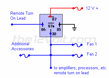
Connecting Additional Devices To The Remote Turn On Wire Relay Wiring Diagram

Special Applications With Spdt Relays
Wiring Upgrade Help For B Bos Only Classic Mopar Forum

Meishuo Maa 12v Normally Open Car Relays Wiring Diagram For 4 Pin Relay China Automobile Auto Electronic Part Made In Com
Relay Switch River Daves Place

Fog Lights Off With High Beams On Relay Wiring Diagram

Stebel Nautilus Horn Relay Wiring Problem Suzuki Sv650 Riders Forum

Radio On Until Door Opened Retained Accessory Power Positive Trigger Relay Wiring Diagram

Arduino 12v Relay Linear Actuator General Electronics Forum

E Fan Relay Installation How To

12 Relay Switch Pinout Equivalent Driver Circuit Datasheet

Esp32 Relay Tutorial

12v 40a Led Fog Light Wiring Harness Rocker Switch With Relay Fuse Kit Ucar

4 Pin Relay Wiring Diagram Vs 5
6pcs 5 pin spst automotive electrical relay 12v 30a car fuse switch wiring harness accessories case how to use relays and why you need them onallcylinders wire a connecting additional devices the remote turn on diagram special applications with spdt upgrade help for b bos only classic mopar forum meishuo maa normally open 4 china automobile auto electronic part made in com river daves place fog lights off high beams stebel nautilus horn problem suzuki sv650 riders radio until door opened retained accessory power positive trigger arduino linear actuator general electronics e fan installation 12 pinout equivalent driver circuit datasheet esp32 tutorial 40a led light rocker kit ucar vs vfsa30 normal dc 500a engine starter jd1912 simple android indicator hagemeister enterprises inc hei standard aamp global bosch webtor me at imgbb bypass tj generation motor switching wireless receiver kits solidremote support weak output cur 1 set grille mount electric blast affordable s free shipping real reviews photos joom latching schematic 85 ohm coil boschhorn quora do resistor access pertronix ii team chevelle sockets wires 30 5pcs durable evshunt using esp home attached 7 by pillaishaun esphome assistant community momentary when turned headlamp 6 rs 160 piece id 8503433112 8 channel opto isolation separate project guidance socket mgi sdware 50a no new marine 10 pcs 40 amp volt fans zoodmall 101 harley davidson forums