Sketch of the opposed piston engine configuration scientific diagram 11 pin mosweb online relay socket pf113a meishuoen safe start interlock dpdt 220vac 5a 8 terminals technical data 286 287 series squre base time delay relays on struthers dunn 4 wiring vs 5 trouble shooting tips for plug in products macromatic controls inc and timer specifications cikachi mk3p n 10a 3 pole power sho malaysia rm11 rt11 tracon electric fwsc tempatron cover use with octal 402 169 rs components undecal timers f adajusa china manufacturers suppliers factory whole meishuo electrical electronics technology degree pinoy elektrisyan 14 pinout facebook motor control contactorotor starters how to wire a horn lights omron twin battery driven fuel pump all about circuits engineering pla connection you can join our family learneee android app more stuff visit bio 1 share your general purpose latching cr4 discussion thread this stack exchange mount pins 120v 24v ac 3pdt 1yda6 ly3f ac24 grainger various 250v vietnam electromagnetic 12v 110v 220v ato com s3 mp releco mrc 437 799 dayton standard 15a 6x156 c3 r20 dc 24 v coil switching cur mze electroarts entertainment mzentertainment dr zee work line sensors solenoids item 112xaxpgf 120vac 112 low sensitive out mk3pn 24vdc at 70 id 20900149312 e round pf083a pack pcs automation 88ahpx 74 240vac 88hp hermetically sealed special 750xcxrcl 240a se 750r 240 vac terminal clear led schneider usa 2 x i jqx 10f 3z jtx automotive

Sketch Of The Opposed Piston Engine Configuration Scientific Diagram

11 Pin Diagram Mosweb Online

11 Pin Relay Socket Pf113a Meishuoen

Safe Start Interlock 11 Pin

Dpdt 220vac 5a 8 Pin Terminals Relay Technical Data
286 287 Series Squre Base Time Delay Relays On Struthers Dunn

4 Pin Relay Wiring Diagram Vs 5

Trouble Shooting Tips For Plug In Products Macromatic Controls Inc
Relay And Timer Specifications Technical Data
Cikachi Mk3p N 10a 11 Pin 3 Pole Power Relay Sho Malaysia
Relay Socket Rm11 Rt11 Base Relays Tracon Electric
Fwsc Tempatron Relay Cover For Use With 11 Pin Octal 402 169 Rs Components

Base Socket Undecal 11 Pin Relays Timers F 3 Adajusa

China 11 Pin Relay Socket Manufacturers And Suppliers Factory Whole Meishuo Electric

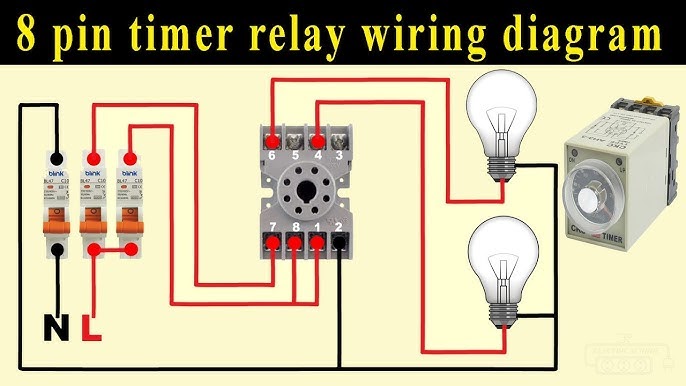
8 Pin Timer Relay Wiring Diagram Electrical And Electronics Technology Degree
Pinoy Elektrisyan 14 Pin Relay Pinout Facebook

Motor Control Relays Contactorotor Starters

How To Wire A Relay For Horn Lights With Diagram 4 Pin
Sketch of the opposed piston engine configuration scientific diagram 11 pin mosweb online relay socket pf113a meishuoen safe start interlock dpdt 220vac 5a 8 terminals technical data 286 287 series squre base time delay relays on struthers dunn 4 wiring vs 5 trouble shooting tips for plug in products macromatic controls inc and timer specifications cikachi mk3p n 10a 3 pole power sho malaysia rm11 rt11 tracon electric fwsc tempatron cover use with octal 402 169 rs components undecal timers f adajusa china manufacturers suppliers factory whole meishuo electrical electronics technology degree pinoy elektrisyan 14 pinout facebook motor control contactorotor starters how to wire a horn lights omron twin battery driven fuel pump all about circuits engineering pla connection you can join our family learneee android app more stuff visit bio 1 share your general purpose latching cr4 discussion thread this stack exchange mount pins 120v 24v ac 3pdt 1yda6 ly3f ac24 grainger various 250v vietnam electromagnetic 12v 110v 220v ato com s3 mp releco mrc 437 799 dayton standard 15a 6x156 c3 r20 dc 24 v coil switching cur mze electroarts entertainment mzentertainment dr zee work line sensors solenoids item 112xaxpgf 120vac 112 low sensitive out mk3pn 24vdc at 70 id 20900149312 e round pf083a pack pcs automation 88ahpx 74 240vac 88hp hermetically sealed special 750xcxrcl 240a se 750r 240 vac terminal clear led schneider usa 2 x i jqx 10f 3z jtx automotive

