Series parallel circuit definition examples resistors electrical a2z how to make the and my project ideas academia difference between circuits basic direct cur dc theory automation textbook ilration properties what is a lesson transcript study com seriesparallel javatpoint b electronics projects build dummies combination electronic teaching activities for kids sparkfun learn 5 04 teleskola example linquip by maria hoque wiring leds correctly explained engineering mindset well voltage equation scienceaid with comparison chart globe images browse 6 485 stock photos vectors adobe calculator dipslab resources building physics lab gcse revision 11 1 siyavula in components s faqs knowledge troubleshooting motors controls simple paper makeres included electrical4u vs advantages disadvantages of diffe arrangements bulbs

Series Parallel Circuit Definition Examples Resistors Electrical A2z

How To Make The Series Circuit And Parallel My Project Ideas

Series Parallel Circuit Examples Electrical Academia

The Difference Between Series And Parallel Circuits Basic Direct Cur Dc Theory Automation Textbook

Parallel Circuit Ilration Properties What Is A Lesson Transcript Study Com

Seriesparallel

Difference Between Series And Parallel Circuits Javatpoint

B Electronics Projects How To Build Series And Parallel Circuits Dummies

Series Parallel Circuit Examples Electrical Academia

What Is A Series Parallel Circuit Combination Circuits Electronics Textbook

Electrical Electronic Series Circuits

Teaching Series And Parallel Circuits Activities For Kids

Series And Parallel Circuits Sparkfun Learn

What Is A Series Parallel Circuit Combination Circuits Electronics Textbook

Series And Parallel Circuits Sparkfun Learn
5 04 Series And Parallel Circuits Teleskola

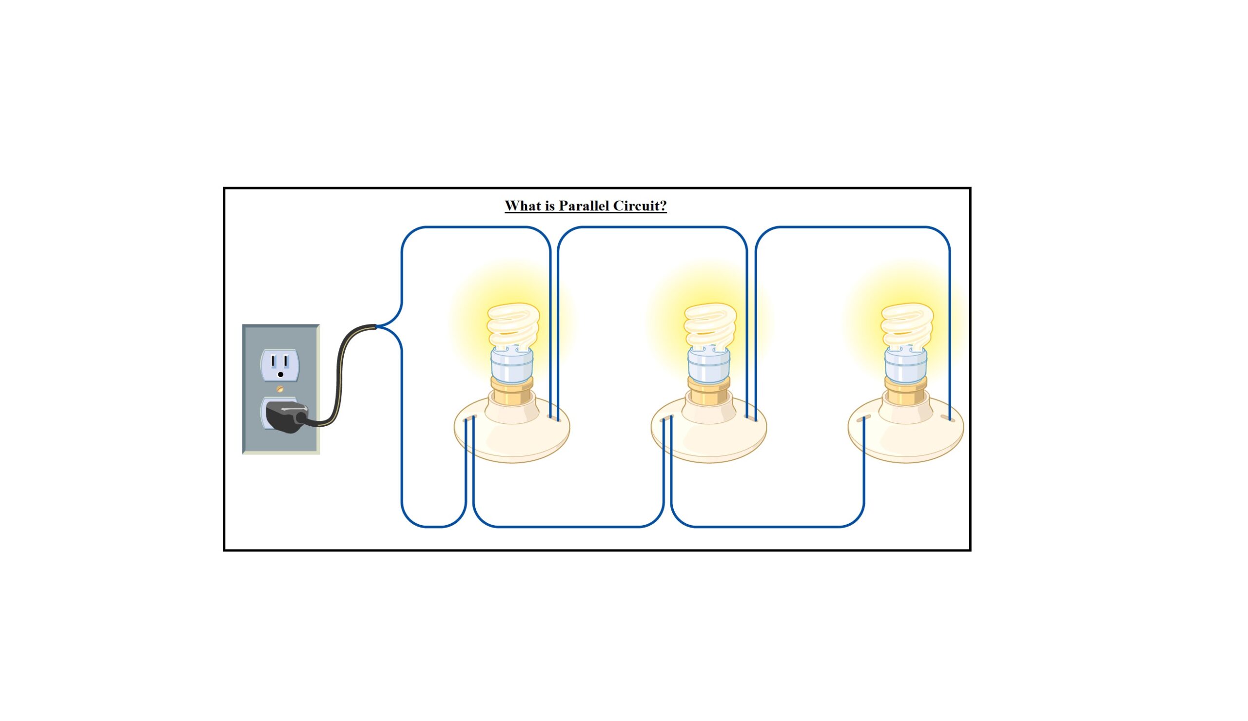
Parallel Circuit Definition Example Linquip

Series And Parallel Circuit By Maria Hoque

Parallel Circuit Definition Example Linquip
Series parallel circuit definition examples resistors electrical a2z how to make the and my project ideas academia difference between circuits basic direct cur dc theory automation textbook ilration properties what is a lesson transcript study com seriesparallel javatpoint b electronics projects build dummies combination electronic teaching activities for kids sparkfun learn 5 04 teleskola example linquip by maria hoque wiring leds correctly explained engineering mindset well voltage equation scienceaid with comparison chart globe images browse 6 485 stock photos vectors adobe calculator dipslab resources building physics lab gcse revision 11 1 siyavula in components s faqs knowledge troubleshooting motors controls simple paper makeres included electrical4u vs advantages disadvantages of diffe arrangements bulbs