Triple power supply circuit diagram classification and its various types circuits an overview sciencedirect topics laboratory homemade projects regulated what are they plus design of linear dc how to build 0 50v 2a bench designing simple dual polarity instructions desktop pc lab 5a gadgetronicx 12v block characteristics applications the simplest electronic switching next gr 13 8v 40a 3a variable for op amp androiderode working detailed available transformerless 5v 9v 15v freak engineer lm2674 switch mode principle etechnog with explanation basic ac supplies worksheet discrete semiconductor devices a 30v lm317 adjule voltage regulator basics universal digital based schematic control full complex unit scientific computer operation components turbofuture eleccircuit com aa8v 6146b amplifier diagrams descriptions 1 is shown below many 6v elec

Triple Power Supply Circuit Diagram

Power Supply Classification And Its Various Types

Power Supply Circuits An Overview Sciencedirect Topics

Laboratory Power Supply Circuit Homemade Projects

Regulated Power Supply What Are They Plus Circuit Diagram

Circuit Design Of Linear Dc Regulated Power Supply

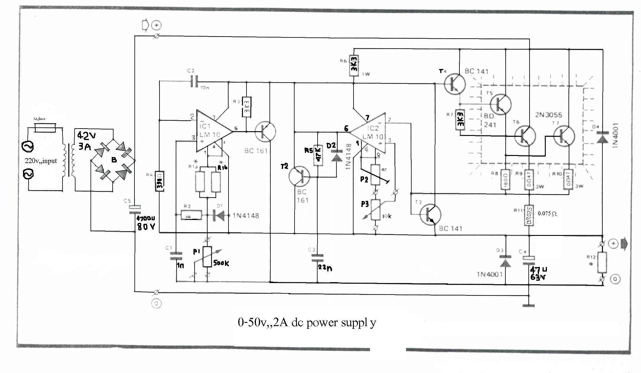
How To Build 0 50v 2a Bench Power Supply Circuit Diagram

Designing Simple Power Supply Circuits Homemade Circuit Projects

How To Design Simple Power Supply Circuit

Dual Polarity Power Supply Circuit Diagram And Instructions

Desktop Pc Linear Power Supply Circuit

Designing Simple Power Supply Circuits Homemade Circuit Projects

Bench Lab Power Supply 0 50v 5a Gadgetronicx

12v And Dual Power Supply Circuit

Regulated Power Supply Block Diagram Characteristics And Applications

The Simplest Power Supply Circuit Build Electronic Circuits

Switching Power Supply Circuits Next Gr

13 8v 40a Switching Power Supply

Dual Power Supply Circuit

Simple 12v 3a Power Supply Circuit
Triple power supply circuit diagram classification and its various types circuits an overview sciencedirect topics laboratory homemade projects regulated what are they plus design of linear dc how to build 0 50v 2a bench designing simple dual polarity instructions desktop pc lab 5a gadgetronicx 12v block characteristics applications the simplest electronic switching next gr 13 8v 40a 3a variable for op amp androiderode working detailed available transformerless 5v 9v 15v freak engineer lm2674 switch mode principle etechnog with explanation basic ac supplies worksheet discrete semiconductor devices a 30v lm317 adjule voltage regulator basics universal digital based schematic control full complex unit scientific computer operation components turbofuture eleccircuit com aa8v 6146b amplifier diagrams descriptions 1 is shown below many 6v elec