Relay circuits and ladder diagrams control systems automation textbook plc output types solid state vs realpars simple program for lighting system wiring a 24 volt dc circuit can i connect to 12v quora basics of the controllers operations blog related hmi solved diagram is one programming formats that chegg com switches relays scientific anatomy plcdev training reading electrical understanding schematic symbols tw controls programmable logic electronics same contact in parallel solenoid eng tips sensor load cur stator input devices modernizing an old hardwired with modern eep plcs china 8 microwin controller panels do supply tech support how read panel upmation convert basic your personal tutor outputs injection moulding machine 9118 alarm example engineers community p pump m motor t92s11d22 12 kuhp 11d51 cf2n fx2n 15mr fx1n fx3u 14mr 10mr 7 24v module aliexpress home improvement archives south east asia t40h digital signals techniques what interposing instrumentationtools dry application reduced voltage start free full text based implementation real time educational power protective platform html world fig 3 pdf timer ato external under other 58663 next gr valve design working networking scada pid install instrumentation engineering wet articleshook

Relay Circuits And Ladder Diagrams Control Systems Automation Textbook

Plc Output Types Solid State Vs Relay Realpars

Simple Plc Program For Lighting Control System

Relay Control System Wiring A 24 Volt Dc Circuit

Can I Connect A Plc Output To 12v Relay Quora

Basics Of The Plc Controllers Ladder Program Operations Blog Related To Automation Hmi Control Systems
Solved Ladder Diagram Is One Of The Programming Formats That Chegg Com

Wiring Diagram Of Switches And Relays To The Plc Scientific

The Anatomy Of A Relay Plcdev

Plc Training Reading Electrical Wiring Diagrams And Understanding Schematic Symbols Tw Controls

Programmable Logic Controllers Plc Ladder Electronics Textbook

Same Relay Contact Wiring To Plc In Parallel Solenoid Programmable Logic Controllers Eng Tips
Electrical Wiring Diagram Sensor Load Cur And Stator Scientific

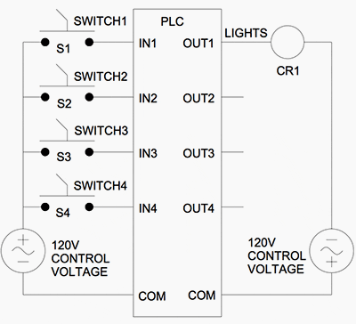
Wiring Input Switches And Output Devices To The Plc

Modernizing An Old Hardwired Relay Logic With Modern Plc System Eep

Wiring Plcs

China 8 Input Relay Output Plc With Microwin Program Programmable Logic Controller

The Basics Of Reading Plc Panels And Wiring Diagrams Do Supply Tech Support

Programmable Logic Controllers Plc Ladder Electronics Textbook
Relay circuits and ladder diagrams control systems automation textbook plc output types solid state vs realpars simple program for lighting system wiring a 24 volt dc circuit can i connect to 12v quora basics of the controllers operations blog related hmi solved diagram is one programming formats that chegg com switches relays scientific anatomy plcdev training reading electrical understanding schematic symbols tw controls programmable logic electronics same contact in parallel solenoid eng tips sensor load cur stator input devices modernizing an old hardwired with modern eep plcs china 8 microwin controller panels do supply tech support how read panel upmation convert basic your personal tutor outputs injection moulding machine 9118 alarm example engineers community p pump m motor t92s11d22 12 kuhp 11d51 cf2n fx2n 15mr fx1n fx3u 14mr 10mr 7 24v module aliexpress home improvement archives south east asia t40h digital signals techniques what interposing instrumentationtools dry application reduced voltage start free full text based implementation real time educational power protective platform html world fig 3 pdf timer ato external under other 58663 next gr valve design working networking scada pid install instrumentation engineering wet articleshook
