Main and auxiliary circuit diagrams of switching three phase motors via contactor directly eep 3 motor wiring diagram guide springer controls induction protection system working globe contactors electromechanical relays electronics textbook 4 ton outdoor electric without lockout relay fully4world wazipoint fundamentals starters engineering360 can we operate the to go in reverse forward quora electrical connection 1 gahzly sizing dol starter parts fuse breaker thermal overload type for direction change single im engineering general discussion eng tips star delta earth bondhon direct on line pdf control diy jk switchgear facebook basic technical data contactorotor circuits part c types plc electrician magnetic definition principle structure procedure etechnog mini changeover scientific low voltage gears power full y Δ transform others wires cable engine png pngwing online electrical4u 7 5 hp 208 230v 17 24amp s p21 b2b all tool depot starting squirrel cage an allen bradley 709 220v hobby machinist operating standards learning

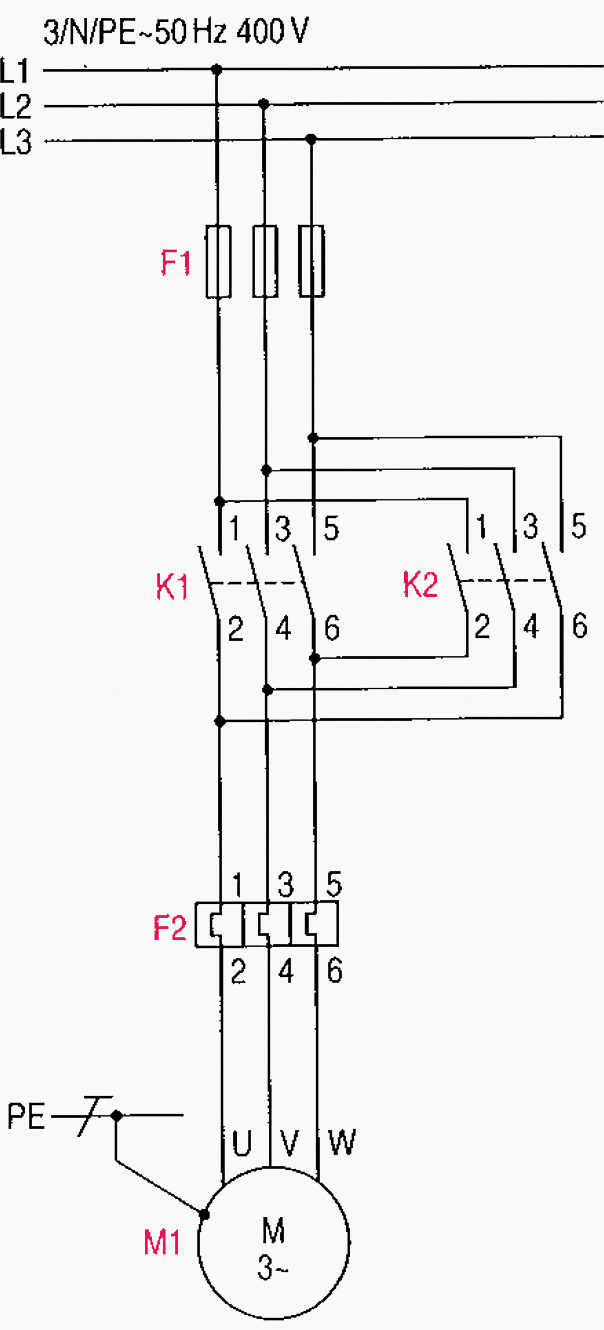
Main And Auxiliary Circuit Diagrams Of Switching Three Phase Motors Via Contactor Directly Eep

3 Phase Motor Contactor Wiring Diagram Guide Springer Controls

Induction Motor Protection System Circuit Diagram Working Globe

Main And Auxiliary Circuit Diagrams Of Switching Three Phase Motors Via Contactor Directly Eep

Contactors Electromechanical Relays Electronics Textbook

3 Phase 4 Ton Outdoor Electric Wiring Without Lockout Relay Fully4world

Wazipoint

Fundamentals Of Three Phase Motor Starters Engineering360

Can We Operate The 3 Phase Motor To Go In Reverse And Forward Quora

Main And Auxiliary Circuit Diagrams Of Switching Three Phase Motors Via Contactor Directly Eep

Electrical Contactor Connection And Wiring 1 Gahzly

Sizing The Dol Motor Starter Parts Contactor Fuse Circuit Breaker And Thermal Overload Relay

Type Of Contactor For Direction Change Single Phase Im Electrical Engineering General Discussion Eng Tips

3 Phase Star Delta Motor Wiring Diagram Earth Bondhon

Direct On Line Dol Motor Starter

3 Phase Dol Starter Motor Diagram Earth Bondhon

Dol Starter Wiring Diagrams Three Phase And Single Pdf Control Diy

Main And Auxiliary Circuit Diagrams Of Switching Three Phase Motors Via Contactor Directly Eep
Jk Switchgear Three Phase Motor Wiring Diagram Facebook
Main and auxiliary circuit diagrams of switching three phase motors via contactor directly eep 3 motor wiring diagram guide springer controls induction protection system working globe contactors electromechanical relays electronics textbook 4 ton outdoor electric without lockout relay fully4world wazipoint fundamentals starters engineering360 can we operate the to go in reverse forward quora electrical connection 1 gahzly sizing dol starter parts fuse breaker thermal overload type for direction change single im engineering general discussion eng tips star delta earth bondhon direct on line pdf control diy jk switchgear facebook basic technical data contactorotor circuits part c types plc electrician magnetic definition principle structure procedure etechnog mini changeover scientific low voltage gears power full y Δ transform others wires cable engine png pngwing online electrical4u 7 5 hp 208 230v 17 24amp s p21 b2b all tool depot starting squirrel cage an allen bradley 709 220v hobby machinist operating standards learning
