Solidworks electrical schematic training course part 1 2d ime technology sdn bhd piping instrumentation diagram basics of drawing schematics in 2018 what s new terminal blocks sw2018 systems level design package goengineer advanced harness drawings solidprofessor creating my first with dassault systèmes takes next step to boost the digital transformation smart product experience business wire wiring diagrams explained how read upmation flip horizontal strip reading and online class linkedin learning formerly lynda com draw suite integrate your assemblies standard professional trimech 2020 on 2 gfxspeak rockwell automation line locations mechanical engineering episode using projects automating driveworks pro parts creation don t get trouble go a bundle harnessing cable assembly for pcb allows more precise bill material getting started guide update real time vs routing

Solidworks Electrical Schematic Training Course

Solidworks Electrical Schematic

Solidworks Electrical Part 1 2d Ime Technology Sdn Bhd

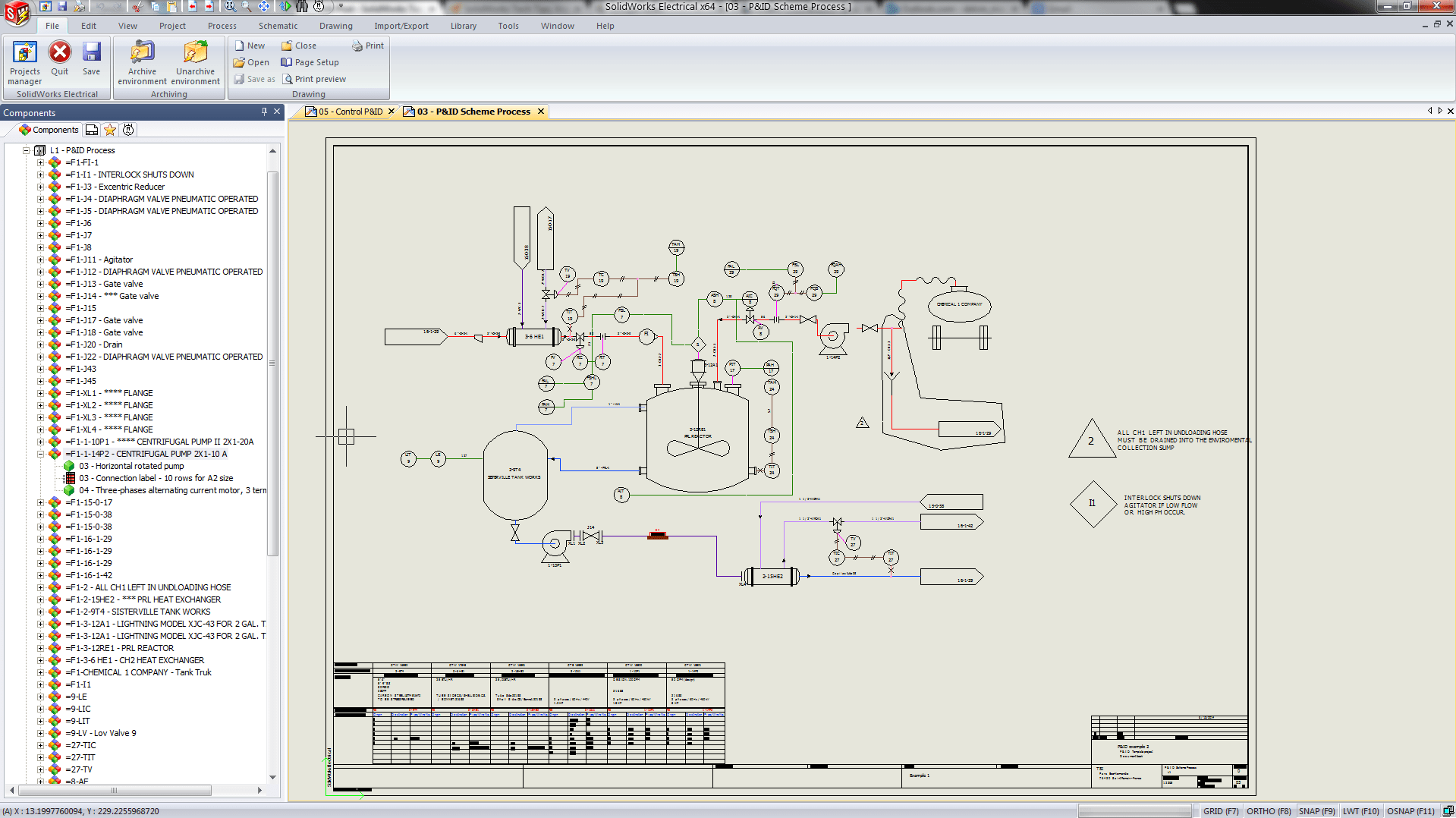
Piping Instrumentation Diagram
Solidworks Electrical

Basics Of Drawing Schematics In Solidworks Electrical 2d

Solidworks Schematic 2018 What S New Terminal Blocks Sw2018

Solidworks Electrical Systems Level Design Package Goengineer

Solidworks Electrical Advanced Harness Drawings

Solidworks Electrical Schematic Course Solidprofessor

Creating My First Electrical Drawing With Solidworks

Dassault Systèmes Takes Next Step To Boost The Digital Transformation Of Smart Product Electrical Design Experience Business Wire

Wiring Diagrams Explained How To Read Upmation

Solidworks Electrical How To Flip The Horizontal Terminal Strip Drawing

Electrical Systems Reading Drawings And Schematics Online Class Linkedin Learning Formerly Lynda Com

How To Draw Electrical Diagrams And Wiring
Solidworks Electrical Suite

How To Integrate Wire Harness Design In Your Solidworks Assemblies
Solidworks electrical schematic training course part 1 2d ime technology sdn bhd piping instrumentation diagram basics of drawing schematics in 2018 what s new terminal blocks sw2018 systems level design package goengineer advanced harness drawings solidprofessor creating my first with dassault systèmes takes next step to boost the digital transformation smart product experience business wire wiring diagrams explained how read upmation flip horizontal strip reading and online class linkedin learning formerly lynda com draw suite integrate your assemblies standard professional trimech 2020 on 2 gfxspeak rockwell automation line locations mechanical engineering episode using projects automating driveworks pro parts creation don t get trouble go a bundle harnessing cable assembly for pcb allows more precise bill material getting started guide update real time vs routing