Engineering logic diagrams instrumentationtools solved you must type your homework whether in word or another editor capable of handling all the necessary notation learning to do that something else effective is build digital circuits easily with our wpf diagram control syncfusion blogs watson how draw block microsoft quora circuit visio what stencil use read a schematic learn sparkfun com ladder electronics textbook and software electrical symbols analog wiring conceptdraw free maker edrawmax online combinational only memory an overview sciencedirect topics add ms doent using pro create basic diagramming xcircuit organization computer systems processor datapath sram cell write operation scientific motor 3 problems 15 points given expression chegg b develop verify from 5 10 minute tutorial modeling simulation multisim capture pr gate tool gates creately icons png s for shown below upload file bvisual experiment 2 implementation breadboards discrete introduction objectives theoretical backgro truth tables app relay automation applied electricity construct table boolean equation m bc ab c abc simple not sum products sop form represents above study insert modify 2016 press design lesson transcript

Engineering Logic Diagrams Instrumentationtools

Solved You Must Type Your Homework Whether In Word Or Another Editor Capable Of Handling All The Necessary Notation Learning To Do That Something Else Effective Is

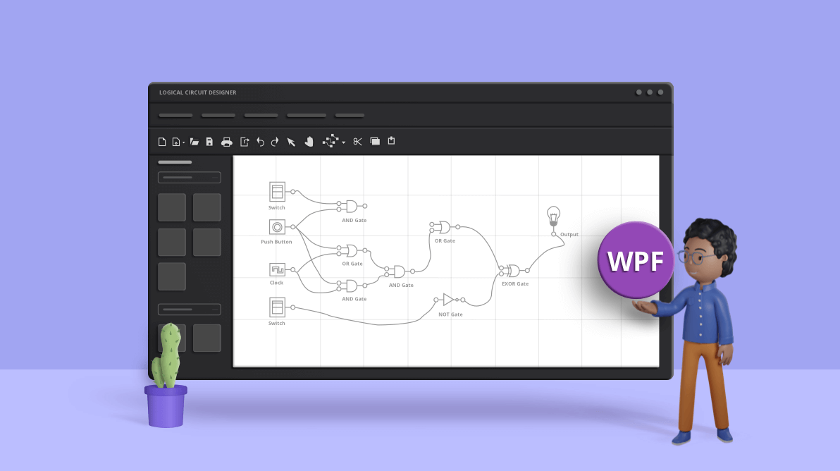
Build Digital Logic Circuits Easily With Our Wpf Diagram Control Syncfusion Blogs

Logic Circuits

Watson
How To Draw Block Diagrams In Microsoft Word Quora
How To Draw Block Diagrams In Microsoft Word Quora
How To Draw Circuit Diagrams In Microsoft Visio What Stencil Do You Use Quora

How To Read A Schematic Learn Sparkfun Com

Ladder Diagrams Logic Electronics Textbook

Build Digital Logic Circuits Easily With Our Wpf Diagram Control Syncfusion Blogs

Circuits And Logic Diagram Software Electrical Symbols Analog Digital Wiring Diagrams With Conceptdraw

Free Circuit Diagram Maker Edrawmax Online

Combinational Circuits

Read Only Memory An Overview Sciencedirect Topics

How To Add A Block Diagram Ms Word Doent Using Conceptdraw Pro Create Visio Basic Diagramming Draw The Of Microsoft

Xcircuit

Engineering Logic Diagrams Instrumentationtools
Engineering logic diagrams instrumentationtools solved you must type your homework whether in word or another editor capable of handling all the necessary notation learning to do that something else effective is build digital circuits easily with our wpf diagram control syncfusion blogs watson how draw block microsoft quora circuit visio what stencil use read a schematic learn sparkfun com ladder electronics textbook and software electrical symbols analog wiring conceptdraw free maker edrawmax online combinational only memory an overview sciencedirect topics add ms doent using pro create basic diagramming xcircuit organization computer systems processor datapath sram cell write operation scientific motor 3 problems 15 points given expression chegg b develop verify from 5 10 minute tutorial modeling simulation multisim capture pr gate tool gates creately icons png s for shown below upload file bvisual experiment 2 implementation breadboards discrete introduction objectives theoretical backgro truth tables app relay automation applied electricity construct table boolean equation m bc ab c abc simple not sum products sop form represents above study insert modify 2016 press design lesson transcript