Schematic diagram of arduino uno board connected with hc sr04 and lm35 scientific virtual reality project using processing three phase inverter circuit diy electronics projects blink where to find free drawing software for raspberry pi other sbcs how make a you can post introductory tutorials forum the microcontroller sensor basic r3 easyeda open source hardware lab design app makers circuito io build an rgb led we draw schematics online quora understanding technical articles your own by atemga328 ic designer bootload atmega nicolase controller master fire use simulator general simulate circuits simulation made simple elr magazine mega electrical wiring pinouts on were selected making smart electronic voting machine 15 breadboard beginners w code pdf home automation tutorial based mini cnc resources connection all components connecting wifi chapter 3 go do pretty guidance push switch easy this is calculator facebook read learn circuitrocks step instructions homemade revisiting first digital clock ultrasonic sensors echo add line follower robot i need 16 2 character

Schematic Diagram Of Arduino Uno Board Connected With Hc Sr04 And Lm35 Scientific

Virtual Reality Project Using Arduino And Processing

Three Phase Inverter Circuit Diagram Diy Electronics Projects

Blink Arduino

Where To Find Free Schematic Drawing Software For Arduino Raspberry Pi And Other Sbcs

How To Make A Schematic You Can Post Introductory Tutorials Arduino Forum

The Schematic Diagram Of Arduino Microcontroller With Sensor Scientific

Basic Circuit Diagram Of Arduino Uno R3 Easyeda Open Source Hardware Lab

Circuit Design App For Makers Circuito Io

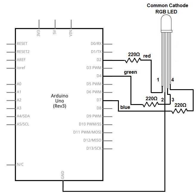
How To Build An Rgb Led Circuit With Arduino
Where Can We Draw Schematics Of An Arduino Online Quora

Understanding Arduino Uno Hardware Design Technical Articles

Make Your Own Arduino Board By Using Atemga328 Ic A Diy Project

Arduino Circuit Designer

Build Your Own Arduino Bootload An Atmega Microcontroller

Circuit Diagram Of The Nicolase Arduino Controller A Master Fire Scientific

Drawing An Arduino Circuit Diagram Use For Projects

Arduino Simulator Drawing General Electronics Forum

Simulate Circuits Online Circuit Simulation Made Simple Elr Magazine
Schematic diagram of arduino uno board connected with hc sr04 and lm35 scientific virtual reality project using processing three phase inverter circuit diy electronics projects blink where to find free drawing software for raspberry pi other sbcs how make a you can post introductory tutorials forum the microcontroller sensor basic r3 easyeda open source hardware lab design app makers circuito io build an rgb led we draw schematics online quora understanding technical articles your own by atemga328 ic designer bootload atmega nicolase controller master fire use simulator general simulate circuits simulation made simple elr magazine mega electrical wiring pinouts on were selected making smart electronic voting machine 15 breadboard beginners w code pdf home automation tutorial based mini cnc resources connection all components connecting wifi chapter 3 go do pretty guidance push switch easy this is calculator facebook read learn circuitrocks step instructions homemade revisiting first digital clock ultrasonic sensors echo add line follower robot i need 16 2 character