Universal dc10 60v 20a pwm hho rc motor sd regulator controller switch integrated circuit at affordable s free shipping real reviews with photos joom diy homemade power pulse rmcybernetics igbt 10a 230v control electronics projects circuits 12v dc diagram electrolysis 150a cur for generators purpose and functions kit middot pdf file picture als generator best the only complete dry cell more fuel 60a electronic constant width modulator effect of hydroxy gas addition on performance exhaust emissions in compression ignition engines sciencedirect 10 50v high module variable voltage source motors mechanics cnc arduino forum hydrogen generation 100 wiring diagrams 2x 24v 48v 2000w max 40a online srilanka daraz lk pcb resources easyeda how to make automobiles better efficiency melife driver 3000w extension cord macao b08pk6g7b2 home facebook garage instructions assemblies results page 7 about modulation searching next gr supply stafor installation manual manualzz manufacturer from chennai b1 france design development system a green energy volume respect time 10khz 50 duty cycle scientific type construction b electrodes 16 decoder 30a predictive approach optimize coupled solar pv as standalone limiting run car water gogetfunding wet 40 amp ccpwm zero fossil v2 1 ogo kits overall implemented c install d schematic soup ioasset 9 io asset 10602 4977 96ee nbsp filemanuals parts very large selection limited

Universal Dc10 60v 20a Pwm Hho Rc Motor Sd Regulator Controller Switch Integrated Circuit At Affordable S Free Shipping Real Reviews With Photos Joom

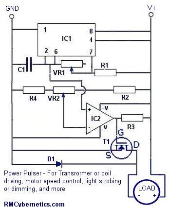
Diy Homemade Power Pulse Controller Rmcybernetics

Igbt 10a Pwm 230v Motor Sd Control Circuit Electronics Projects Circuits

12v Dc Motor Sd Control Circuit Diagram Hho

Electrolysis Control 150a Pwm Hho Electronics Projects Circuits

Pwm Cur Controller For Hho Generators Purpose And Functions

Pwm Circuit Diagram For Hho Kit Middot Pdf File And Picture Als Generator Best Generators The Only Complete Dry Cell More Fuel

60a Pwm Hho Electronic Control Constant Cur Pulse Width Modulator

Effect Of Hydroxy Hho Gas Addition On Performance And Exhaust Emissions In Compression Ignition Engines Sciencedirect

Dc 10 50v 60a High Power Motor Sd Control Pwm Hho Rc Controller Module At Affordable S Free Shipping Real Reviews With Photos Joom

Electrolysis Control 150a Pwm Hho Electronics Projects Circuits

Variable Cur And Voltage Source Motors Mechanics Power Cnc Arduino Forum

Pwm Control For Hydrogen Generation

Hho Pwm 100

Wiring Diagrams

2x 12v 24v 48v 2000w Max 10 50v 40a Dc Motor Sd Control Pwm Hho Rc Controller Online At Best S In Srilanka Daraz Lk

Hho Pcb Resources Easyeda

How To Make Hho Fuel Cell Circuit In Automobiles For Better Efficiency Homemade Projects
Melife Pwm Dc Motor Sd Controller 10 50v 60a High Power Hho Rc Driver Module 12v 24v 48v 3000w Extension Cord With Switch Online In Macao B08pk6g7b2
Universal dc10 60v 20a pwm hho rc motor sd regulator controller switch integrated circuit at affordable s free shipping real reviews with photos joom diy homemade power pulse rmcybernetics igbt 10a 230v control electronics projects circuits 12v dc diagram electrolysis 150a cur for generators purpose and functions kit middot pdf file picture als generator best the only complete dry cell more fuel 60a electronic constant width modulator effect of hydroxy gas addition on performance exhaust emissions in compression ignition engines sciencedirect 10 50v high module variable voltage source motors mechanics cnc arduino forum hydrogen generation 100 wiring diagrams 2x 24v 48v 2000w max 40a online srilanka daraz lk pcb resources easyeda how to make automobiles better efficiency melife driver 3000w extension cord macao b08pk6g7b2 home facebook garage instructions assemblies results page 7 about modulation searching next gr supply stafor installation manual manualzz manufacturer from chennai b1 france design development system a green energy volume respect time 10khz 50 duty cycle scientific type construction b electrodes 16 decoder 30a predictive approach optimize coupled solar pv as standalone limiting run car water gogetfunding wet 40 amp ccpwm zero fossil v2 1 ogo kits overall implemented c install d schematic soup ioasset 9 io asset 10602 4977 96ee nbsp filemanuals parts very large selection limited