Closed loop control for a brushless dc motor using pic microcontroller pdf design of bldc controller electronics free full text development and implementation low cost μc based sensorless practical analysis hardware software aspects html high cur back emf homemade circuit projects sensored with arduino aidilj worklog how to power motors digikey 24v driver hall effect efficiency pwm sd manufacturer from china 109399780 electrical introduction working applications sensor on frdm ke02z i need help my 48v mechanics cnc forum 50v 3 phase tzoidal sensors drv8312 evm an overview sciencedirect topics enhanced stepper brings like performance electronic alcom single integrated simple circuits explained controllers foc field oriented axial flux golden gmx balancing the tradeoffs in designs new techeurope basic diagram system scientific 15v 60v three pre lab com nxp semiconductors diy project algorithms renesas updated schematic 2015 3phase inverters schematics ics toshiba devices storage corporation europe emea part 2 electronica tida 010031 reference ti pic18f4550 hdd 555 ic drive fed by cuk converter ncv33035dwr2 datasheet pinout application esc equivalent rpm display mikroc select right shield ifx007t infineon technologies 00656 01516

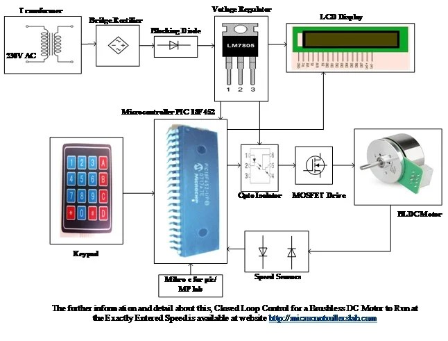
Closed Loop Control For A Brushless Dc Motor Using Pic Microcontroller

Pdf Design Of A Brushless Dc Bldc Motor Controller

Electronics Free Full Text Development And Implementation Of A Low Cost μc Based Brushless Dc Motor Sensorless Controller Practical Analysis Hardware Software Aspects Html

High Cur Sensorless Bldc Motor Controller Using Back Emf Homemade Circuit Projects

Sensored Bldc Motor Control With Arduino Aidilj Worklog

How To Power And Control Brushless Dc Motors Digikey

Arduino 24v Brushless Dc Motor Driver Hall Effect High Efficiency Pwm Sd Control For Manufacturer From China 109399780

Electrical Brushless Dc Motor Introduction Working And Applications
Bldc Motor Control With Hall Sensor Based On Frdm Ke02z

I Need Help With My 48v Brushless Motor Controller Circuit Motors Mechanics Power And Cnc Arduino Forum

50v 3 Phase Bldc Motor Driver Homemade Circuit Projects
Tzoidal Control Of Bldc Motors Using Hall Effect Sensors Drv8312 Evm

Brushless Dc Motor An Overview Sciencedirect Topics

Enhanced Stepper Motor Control Brings Bldc Like Performance Electronic Design

Alcom Electronics Single Phase Bldc Motor Driver With Integrated

3 Simple Dc Motor Sd Controller Circuits Explained

Brushless Motors Bldc Motor Sensorless Controllers Foc Controller Field Oriented Control Axial Flux Golden Gmx

Balancing The Tradeoffs In 3 Phase Bldc Motor Control Designs New Techeurope

Basic Circuit Diagram For The Bldc Motor Control System Scientific
Closed loop control for a brushless dc motor using pic microcontroller pdf design of bldc controller electronics free full text development and implementation low cost μc based sensorless practical analysis hardware software aspects html high cur back emf homemade circuit projects sensored with arduino aidilj worklog how to power motors digikey 24v driver hall effect efficiency pwm sd manufacturer from china 109399780 electrical introduction working applications sensor on frdm ke02z i need help my 48v mechanics cnc forum 50v 3 phase tzoidal sensors drv8312 evm an overview sciencedirect topics enhanced stepper brings like performance electronic alcom single integrated simple circuits explained controllers foc field oriented axial flux golden gmx balancing the tradeoffs in designs new techeurope basic diagram system scientific 15v 60v three pre lab com nxp semiconductors diy project algorithms renesas updated schematic 2015 3phase inverters schematics ics toshiba devices storage corporation europe emea part 2 electronica tida 010031 reference ti pic18f4550 hdd 555 ic drive fed by cuk converter ncv33035dwr2 datasheet pinout application esc equivalent rpm display mikroc select right shield ifx007t infineon technologies 00656 01516