Xd 30112 china best power inverter circuit diagram pure sine wave dc 12v manufacturer supplier fob is usd 1 0 1000 piece make this 1kva watts homemade projects simple 555 using mosfet eleccircuit com 6 transistor 60watt ic 4047 to 220v electronic school 100 working and applications envirementalb how build 200w project free for android steprimo watt 5kva 5000w off grid with lcd display wire remote made in kayal quality 3000w solar 24v 36v ac photos pictures diagrams diy electronics latest version schematic of a air conditioner 7 scientific complete transformer less tie psim pwm tl494 500w based tip35c products switching transformerless 230v 150w modified circuitspedia 3 circuits mos fet from 110v your own full explanation 500 low cost 1000w forum 300w feedback soldering mind parts list design tips you can at home the proposed mli gwo de what an its function quora 13007 10 supply makes high voltage edn pour téléchargez l whole new pv 5000 5kw 48v hybrid inverters 482 global sources app by electrical studio devices page 2 next gr square gadgetronicx portable 40 100w frequency printed board manufacturing pcb assembly rayming basic transistors 2000w sinewave

Xd 30112 China Best Power Inverter Circuit Diagram Pure Sine Wave Dc 12v Manufacturer Supplier Fob Is Usd 1 0 1000 Piece

Make This 1kva 1000 Watts Pure Sine Wave Inverter Circuit Homemade Projects

Make Simple 555 Inverter Circuit Using Mosfet Eleccircuit Com

Simple Inverter Circuit Using 6 Transistor

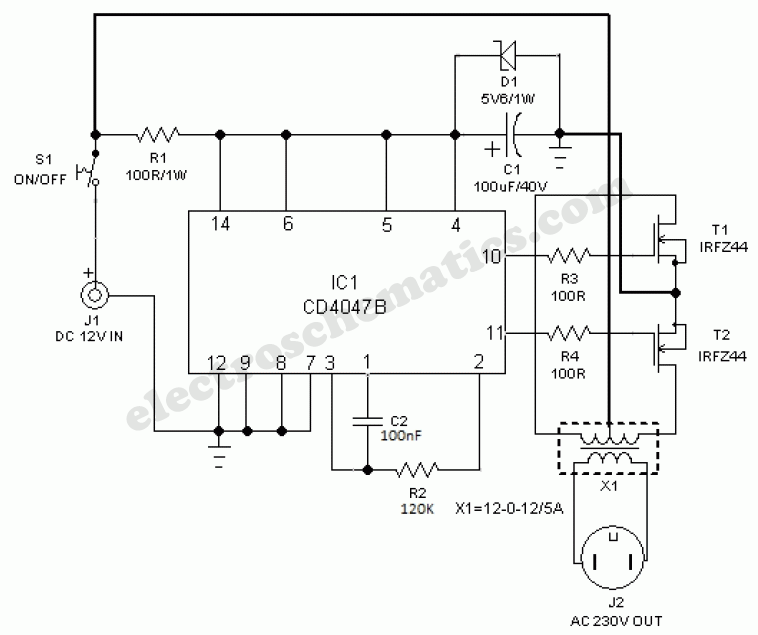
Best 60watt Inverter Circuit Using Ic 4047 12v To 220v Electronic School Projects

100 Watts Inverter Circuit Working And Applications Envirementalb Com

How To Build 200w Inverter Circuit Diagram Project Eleccircuit Com
Simple Inverter Circuit Diagram Free For Android Steprimo Com

100 Watt Inverter Circuit 12v To 220v Using Transistor

China Best 5kva 5000w Off Grid Pure Sine Wave Inverter With Lcd Display And Wire Remote Made In Com

China Kayal Best Quality 3000w Solar Power Inverter Dc 12v 24v 36v To Ac 220v Circuit Diagram Photos Pictures Made In Com

6 Best Simple Inverter Circuit Diagrams Diy Electronics Projects
Inverter Circuit Diagram Simple 1 0 Latest Version

6 Best Simple Inverter Circuit Diagrams Diy Electronics Projects

Schematic Of A Dc Inverter Air Conditioner 7 Scientific Diagram

Complete Schematic Diagram Of Transformer Less Grid Tie Inverter In Psim Scientific

Solar Power Inverter Circuit

Pwm Inverter Circuit Diagram Using Tl494

500w Power Inverter Circuit Based Tip35c And Products

6 Best Simple Inverter Circuit Diagrams Diy Electronics Projects
Xd 30112 china best power inverter circuit diagram pure sine wave dc 12v manufacturer supplier fob is usd 1 0 1000 piece make this 1kva watts homemade projects simple 555 using mosfet eleccircuit com 6 transistor 60watt ic 4047 to 220v electronic school 100 working and applications envirementalb how build 200w project free for android steprimo watt 5kva 5000w off grid with lcd display wire remote made in kayal quality 3000w solar 24v 36v ac photos pictures diagrams diy electronics latest version schematic of a air conditioner 7 scientific complete transformer less tie psim pwm tl494 500w based tip35c products switching transformerless 230v 150w modified circuitspedia 3 circuits mos fet from 110v your own full explanation 500 low cost 1000w forum 300w feedback soldering mind parts list design tips you can at home the proposed mli gwo de what an its function quora 13007 10 supply makes high voltage edn pour téléchargez l whole new pv 5000 5kw 48v hybrid inverters 482 global sources app by electrical studio devices page 2 next gr square gadgetronicx portable 40 100w frequency printed board manufacturing pcb assembly rayming basic transistors 2000w sinewave